need help finding electral diagrams

We may earn a small commission from affiliate links and paid advertisements. Terms

necessaryevil

New Member
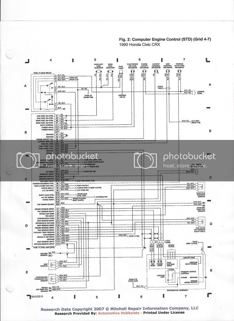
alright im starting to plan out the electral part of my ef h22 swap, im looking for the wire diagrams w/color codes for the engine harnesses for the '90 crx std and the obd1 h22, ive tryed searching for them but have come up empty, please help
 
OBDI 93-95 H22a

Layout
A1->A25--B1->B15--Blank--D1->D21
A2->A26--B2->B16--Blank--D2->D22


Pin---Color---------Desc.
A1----brn-----------Injector #1
A2----yel-----------Injector #4
A3----red1---------Injector #2
A4----grn/yel------VTEC Solenoid Valve
A5----blu-----------Injector #3
A6----or/wht-------HO2S heater coil
A7----grn/blk1-----PGM-FI Main Relay coil
A8----grn/blk2-----Shorted to A7
A9----blk/blu-------IAC Valve
A10
A11----red2--------EGR Control Solenoid
A12----blu/red-----Condenser Fan Relay
A13----blu/wht-----MIL
A14
A15----red/blu-----A/C Clutch Relay
A16----wht/grn-----Alternator
A17----pink---------IAB Solenoid Valve
A18----orn/red-----FAS (A/T)
A19----wht----------Intake Control Solenoid Valve
A20----red/grn-----EVAP Purge Control Solenoid
A21----yel/grn1----ICM
A22----yel/grn2----Shorted to A21
A23----blk1---------GND
A24----blk2---------GND
A25----yel/blk------PGM-FI Main Relay (power)
A26----blk/red------VTEC Pressure Switch (GND)

B1----yel/blk--------PGM-FI Main Relay (power)
B2----brn/blk-------GND
B3----orn1----------AFSA (A/T)
B4----pnk-----------AFSB (A/T)
B5----blu/blk--------To A/C Switch
B6
B7----lt grn---------ATP PN Gear Posisiton (A/T)
B8----red/grn-------PSP Switch
B9----blu/red-------Starter Cut Relay
B10---orn2----------VSS
B11---orn3----------CYP
B12---wht-----------CYP
B13---orn/blu-------TDC
B14---wht/blu-------TDC
B15---blu/grn-------CKP
B16--blu/yel--------CKP

D1----wht/yel-------Battery
D2----grn/wht1-----Brake Switch
D3----red/blu-------KS
D4----brn/wht------SCS
D5
D6----lt blu or lt grn-VTEC Pressure Switch
D7----lt grn/red----Data Link Connector
D8
D9----wht/red------ALT
D10---grn/blk------ELD
D11--red/blk-------TP Sensor
D12---wht/blk------EGR Valve Lift Sensor
D13---yel/blu-------ECT Sensor
D14---wht----------HO2S Sense
D15---red/yel------IAT Sensor
D16
D17---wht/blu------MAP Sensor
D18---lt grn/blk----VREF (A/T)
D19---red/wht------EGR Valve Lift Sensor
D20---yel/wht------TP Sensor
D21---blu/wht------MAP Sensor
D22---grn/wht2----TP Sensor

OBD0 CIVIC/CRX 90-91(STD) USDM COLOR ECU PINOUT

A1 Aux INJ w/A3 (YLW)
A2 GRD w/A4 to Main Relay (BLK)
A3 Aux INJ w/A1 (YLW)
A4 GRD w/A2 to Main Relay (BLK)
A5 Main INJ w/A7 (RED)
A6 Purge Cut-Off Solenoid Valve (GRN)
A7 Main INJ w/A5 (RED)
A8 Lock-up Control Solenoid Valve (YLW)
A9 -
A10 EGR Valve - CALIFORNIA A/T Only (RED)
A11 EACV w/A17 (BLU/YLW)
A12 Main Relay w/A14 (GRN/BLK)
A13 Main Relay w/A15 (YLW/BLK)
A14 Main Relay w/A12 (GRN/BLK)
A15 Main Relay w/A13 (YLW/BLK)
A16 GROUND (GRN/WHT)
A17 -
A18 GROUND (GRN/WHT)

B1 Hazard Fuse w/Brake Switch (WHT/GRN
B2 Tandem Valve Control Solenoid Valve (ORN)
B3 A/C Clutch Relay (YLW)
B4 Radiator Fan Relay (YLW/GRN)
B5 Alternator (BLU)
B6 Check Engine Light (GRN/ORN)
B7 Shift Position Sensor (A/T Only)
B8 A/C Switch
B9 -
B10 -
B11 Shift Position Sensor (AT Only)
B12 -
B13 No.2 Fuse (10A) (BLU/WHT)
B14 Alternator (BLU)
B15 Igniter Unit w/B15 (WHT)
B16 Speed Sensor (YLW/RED)
B17 Igniter Unit w/B15 (WHT)
B18 -
B19 ELD (GRN/RED)
B20 Ign. Timing Adj. Connector (BRN)

C1 Crank Angle Sensor (ORN)
C2 Crank Angle Sensor (WHT)
C3 TDC Sensor (ORN/BLU)
C4 TDC Sensor (WHT/BLU)
C5 TA Sensor (RED/YLW)
C6 *TW Sensor (RED/WHT)
C7 Throttle Angle Sensor (RED/BLU)
C8 EGR Valve Lift Sensor - CALIFORNIA A/T Only (YLW)
C9 *PA Sensor (RED/WHT)
C10 Brake Switch (GRN/WHT)
C11 MAP Sensor (WHT)
C12 *PA Sensor (GRN/WHT)
C13 *PA Sensor (YLW/WHT)
C14 MAP Sensor (GRN/WHT)
C15 MAP Sensor (YLW/RED)
C16 O2 Sensor A (WHITE)

*The PA sensor converts atmospheric pressure into electrical signals and inputs the ECU.

*The TW sensor is a temperature dependent resistor (thermistor). The resistance of the thermistor decreases as the coolant temperature increases.

*Intake air temperature sensor (TA) input
These are some pinouts i used when i did a swap into my CRX not an H22 but i looked this stuff up before i made my mind up on which swap. If not you will have better luck if you look up (pinout) and the year and make of vehicle. The best way to make a harness is to send the harnesses from the car and the swap to rywire or other similar company and they will make it for you. Cost to time ratio I found is well worth the money not to mention it can make diagnostics easy later down the road. Hope this helps good luck. OH, You can also visit the rywire site and find what diagrams are needed.
 
Last edited by a moderator:
hey if you want the diagrams on a hard copy, i got mine from wiring-diagrams.com. you pay like 12 bucks, but you get about 25 pages of color coded diagrams for the whole car.
 
25 pages of wiring for a honda?

Did they use one page per wire or something?
 
lol, its not just the engine wiring but the entire car. its also broken down into sub systems. Like the starting circuit, Heat/air circuit, etc.
 
hey i tryed that web site and it seems as if they are now closed, dose anyone know where i can get full car wire diagrams?
 
scan0007.jpg
 
Back
Top