danherman
206Raincityed7
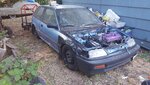
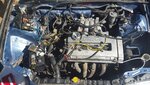
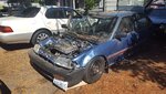
I have a 91 ef. Origa navy dual point. Has been converted to multi and obd1 ecu/ bay for ls v,,
I have a re pined jumper I'll do whatever with and a fresh untouched one minus the male end of the ten or twelve wire connector for 4 wire 02 v tech ect..
I got it back from being stolen and replaced with same components. I had a local shop do the fuel injection and obd1 conversion a long time ago. Now that I am trying to get her going I can get ignition functions as far as lights according starter but I haven't been able to get fuel. I have pump action I am properly pinned into my p28 a1,3,5,7 and a15 as pwr. Do I need resistor box? I have obd 1 injectors. Also there are two wire from dizzy not sure if original color but they run thru drivers side into ignition and fuse box I believe. If u have a a to z on how to do whole thing I'll start fresh but if u know anything I don't and think it may have to do with those wires. I'd like help. I moved c1 ,2 over to b 10 and 12, witch were supposed to be open on my harness but 10 had a white/red wire. I believe it ran to dizzy but it's not plugged in anywere. Being a shop did it and I have a wire that according to the diagrams I have shouldn't be there I'm just about confused at this point. Harness schematics, jumper pins and ecu, if I can obtain those from someone I will just start deleting and running my own harness pin to component in the areas in witch I feel may be a problem. I have 8 pinobd1 dizzy only 7 used. I'm mainly concerned about the dizzy wires not being hooked up properly. Everything says move c 1 2to b10 12 but the wires to ignition and like I said fuse box I believe are the ones I'm being told to take to c pins on ecu after you open them up. Does this mean splice them at dizzy. Idk I figure I need this both ways. I believe they're crank pos. Could be wrong but thats why I'm asking. Help