DIY: Custom Catch Can install
Tools needed:
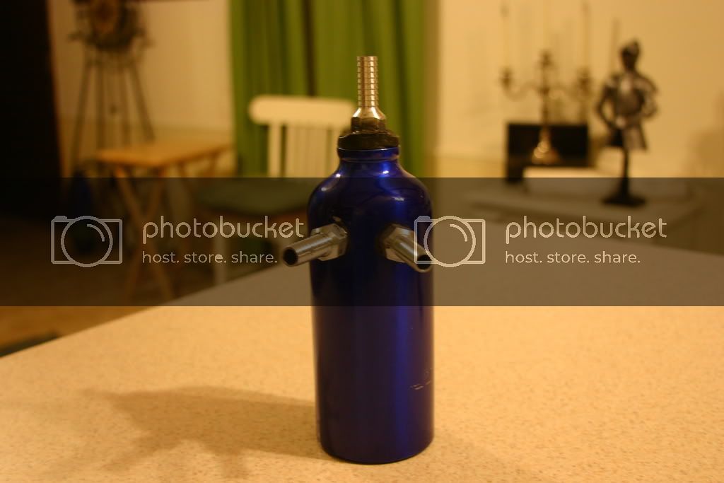
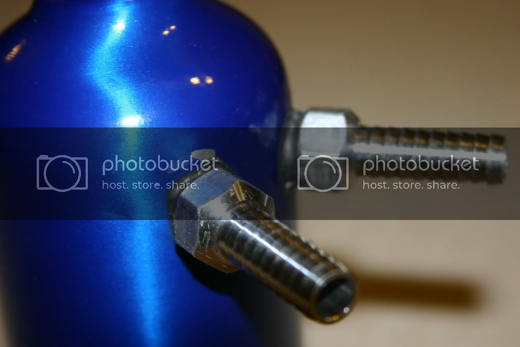
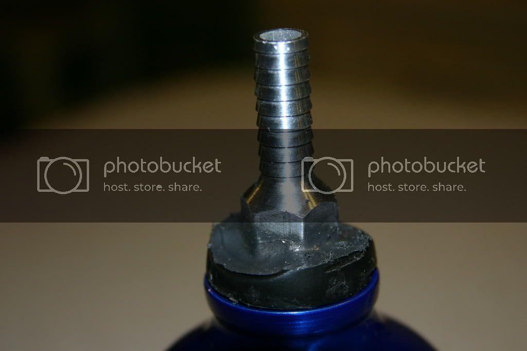
Your custom catch can
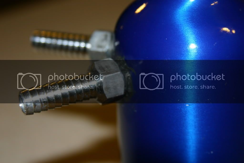
An assortment of hose barbs
several feet of hose
pliers
3/8 Brass hose barb, male on both end.
***Note: You don't have to go in this order.. It's just how I did it.
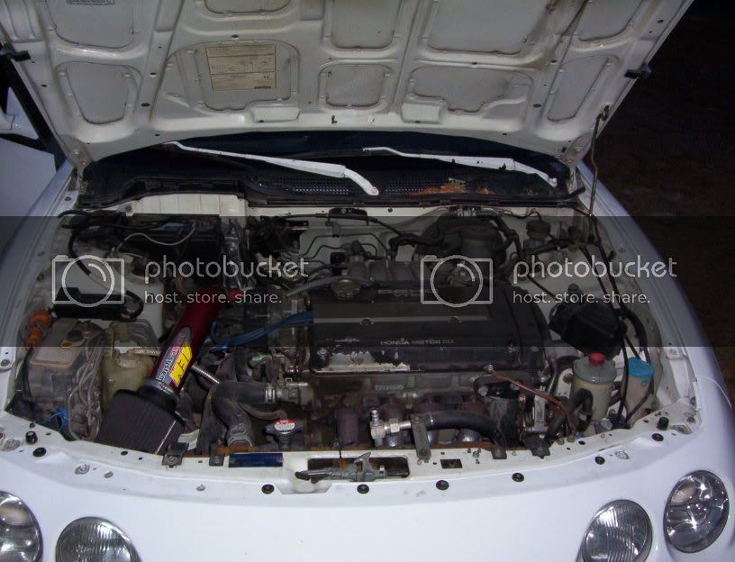
Step 1: Open da hood
") Step 2:
Step 2: Remove your strut bar/Intake piping. Pretty simple.
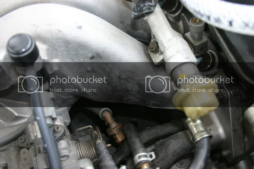
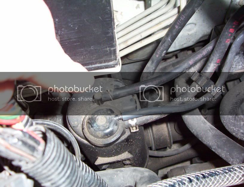
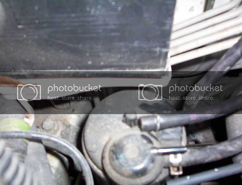
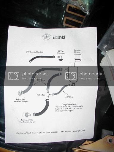
Step 3: Remove the PCV valve so you can remove the hose connecting it to the IM. Took me a good 20 mins to get it. Hardest part of the whole damn thing. It's the lil brown things near the bottom that is sticking up and has the hose connected to it.
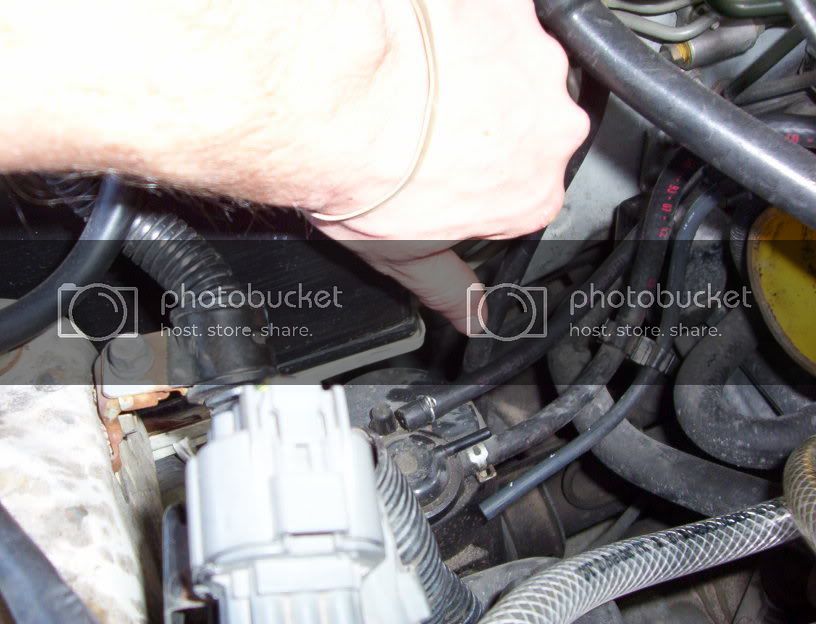
Step 4: Connect the hose running from the IM to the hose thats going to be running to the catch can, via the brass hose barb. Leave the hose long so you can cut it to the correct length later on. Also, add hose from the PCV valve so it will run to the catch can.
Step 5: Move out from the hood and get your can.
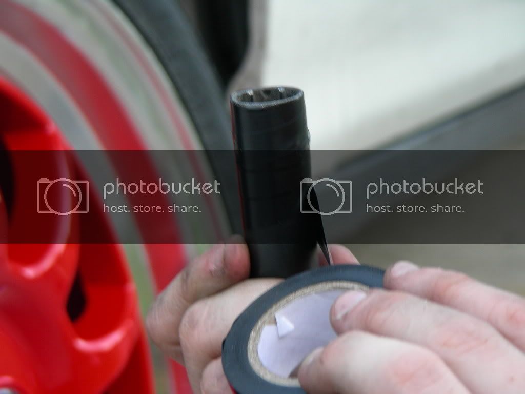
Step 6: Stuff the can with your filter material... In this case, panty hose

I think Eli's imagining him wearing them. So you know, they are NEW.
Step 7: Make sure they are breatheable......... No comment...
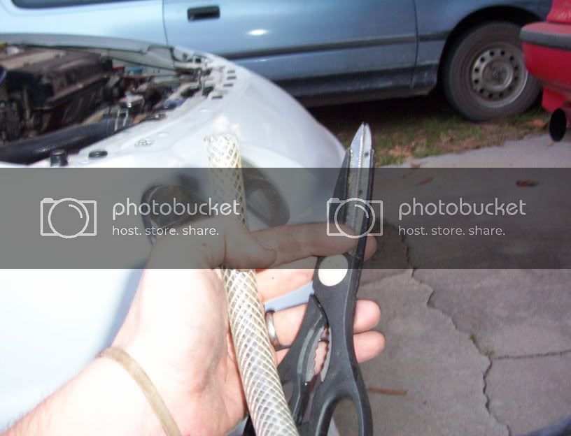
Step 8: Install the can where you want it and cut the hose to length. Using the clear hose, as I did, I found out some scissors are the best way to cut it.
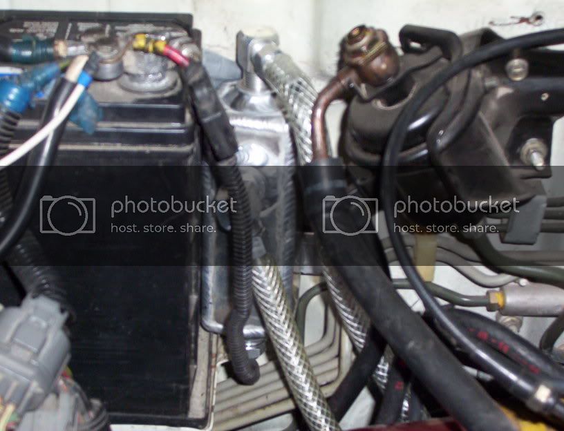
Step 9: Install the can and hook up your hoses! This is the simplest catch can design.. Simply a hose running from the PCV to the can, then one running OUT of the can into the IM.
Danger!!!! Where I was going to originally mount my can, I neded to remove some hoses from the charcoal canister.. Unfortunately, the nipples on it break pretty easily =(
I simply put a screw in the hose and the broken nipple and smeared some gasket maker around it. Good as new =)
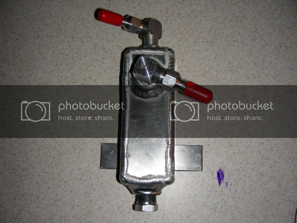
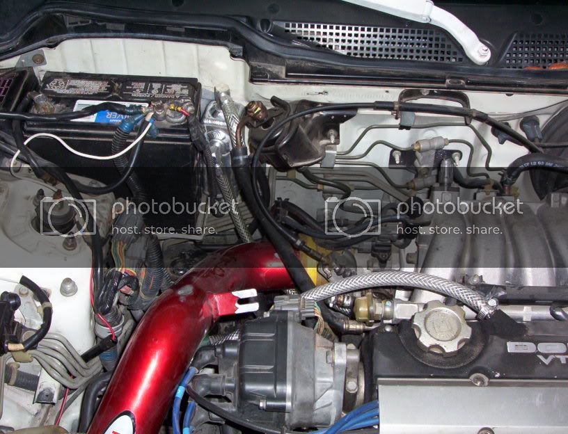
And there you have it. My installed catch can. Notice I ditched my previous can, since this one was much more compact and will function the same.

 Thats some true ninJa stuff there man
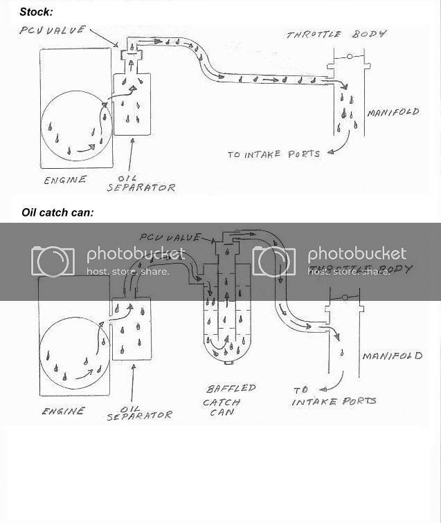

 And from the many threads I"ve read on Team_integra.. This is a highly debated topic, on if you should have a line running from your valve cover to the catch can.
 You guys just hate me (runs away crying)